The "MOVI-PLC® I/O system C" combines high performance and the latest functions with a sophisticated mechanical concept in a compact design that can be precisely adapted to the requirements of the application.
MOVI-PLC® I/O system C – Our portfolio
-
 Bus coupler
-
 Digital input and output modules
-
Analog input and output modules
-
 Safety modules
-
Function modules
-
 Modules for power supply, distribution, and accessories
Bus coupler
| Module | Description | Properties | Data sheet |
|---|---|---|---|
| OCE12C | Bus coupler |
|
To data sheet |
| OCC11C | Bus coupler |
|
To data sheet |
Digital input and output modules
| Module | Description | Properties | Data sheet |
|---|---|---|---|
| ODI24C | Digital input module |
|
To data sheet |
| ODI42C | Digital input module |
|
To data sheet |
| ODI43C | Digital input module |
|
To data sheet |
| ODI81C | Digital input module |
|
To data sheet |
| ODO21C | Digital output module |
|
To data sheet |
| ODO41C | Digital output module |
|
To data sheet |
| ODO81C | Digital output module |
|
To data sheet |
| ODO82C | Digital output module |
|
To data sheet |
Analog input and output modules
| Module | Description | Properties | Data sheet |
|---|---|---|---|
| OAI42C | Analog input module |
|
To data sheet |
| OAI41C | Analog input module |
|
To data sheet |
| OAI44C | Analog input module |
|
To data sheet |
| OAI45C | Analog input module |
|
To data sheet |
| OAO42C | Analog output module |
|
To data sheet |
| OAO41C | Analog output module |
|
To data sheet |
Safety modules
| Module | Description | Properties | Data sheet |
|---|---|---|---|
| OFI41C | Safe digital input |
|
To data sheet |
| OFO41C | Safe digital output |
|
To data sheet |
Function modules
| Module | Description | Properties | Data sheet |
|---|---|---|---|
| OSM11C | Analog input DMS |
|
To data sheet |
| OSM12C | SSI module |
|
To data sheet |
| OSM13C | Counter module |
|
To data sheet |
| OSM14C | Counter module |
|
To data sheet |
| OEM12C | Energy measurement module |
|
To data sheet |
| ORS11C | RS422/485 Interface |
|
To data sheet |
Modules for power supply, distribution, and accessories
| Module | Description | Properties | Data sheet |
|---|---|---|---|
| OPV81C | Potential distributor |
|
To data sheet |
| OPV82C | Potential distributor |
|
To data sheet |
| OPV41C | Potential distributor |
|
To data sheet |
| OPM11C | Power supply module |
|
To data sheet |
| OZB11C | Bus cover |
|
To data sheet |
| OZS11C | Shield bus carrier |
|
To data sheet |
Ready for anything with MOVI-PLC® I/O system C

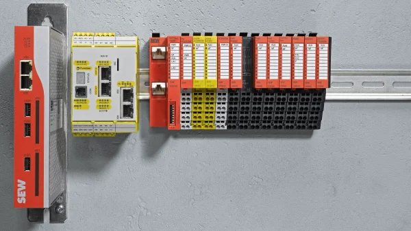
In combination with the new MOVI-C® CONTROLLER portfolio, the product portfolio of SEW-EURODRIVE and external field units provides for an ideal interaction. As a comprehensive solution, the I/O system combines high performance and the latest functions with a well thought-out mechanical concept.
EtherCAT® and CANopen interface modules are available for data exchange with the controller when using this solution. The I/O modules are equipped with a power module for power supply and support up to 64 electronics modules on the backplane bus.
A module unit consists of a terminal module and an electronics module. These are connected with a secure sliding and locking mechanism. The terminal module combines clamps, a fixture for the electronics module and the backplane bus connector. In case of servicing, only the electronics module is exchanged by simply pulling it out of the terminal module – the wiring and mounting on the 35 mm DIN profile rail remains the same. The electronics modules can be supplied with voltage and/or divided into separate potential groups by using additional supply modules. The terminals are arranged on the terminal module in a step-shaped manner using the proven and particularly safe contacting spring-clamp technology in this way enabling fast, clear and safe wiring. The integrated status LEDs and the labeling strips on the front of the electronics modules ensure a channel-specific, clear assignment and readability of channel states. The backplane bus concept with a speed of 48 Mbit/s makes for very short response times.
Ask us for advice
- Our experts are familiar with your industry and requirements
- Our global network ensures we are close at hand wherever and whenever you need us
- We have the expertise and tools to provide you with the best possible support and advice
Your benefits
-
High-performance bus
Transmission rate of 48 Mbit/s – Very fast response time of up to 20 μs – One terminal module for all signal and function modules -
Ease of installation/maintenance
Easy installation due to secure sliding mechanism – Click connection for quick mounting of the shield connection on the module – Coding to prevent from mixing up modules, etc. -
Space-saving connection technology
Space-saving, step-shaped wiring level with spring clamp technology – Easy module replacement due to upright wiring – High modularity due to 2-, 4-, 8-channel modules -
Clear labeling
Labeling strips for individual marking per channel – Status LEDs with direct assignment on the labeling strip – Pin assignment and wiring diagrams on each module -
Clear status and diagnostic displays
Display of diagnostics and channel states via LEDs – Clear assignment and readability of channel states – Detailed diagnostics of each electronics module in the system